What is the significance of the wires of the 18-pin interface connector found in GV600 Asset Tracker?

Modified on Wed, Oct 13, 2021 at 5:36 AM

The GV600M Tracker has an 18-pin interface connector that contains the connections for power, I/O, TTL. The sequence and definition of the 18-pin connector are depicted in the following figure:


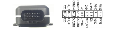
   Figure: The 18-pin Connector on the GV600MG


The below table has Standard Cable Color definitions for wires of GV600MG: 


Pin No

Color

Definition

Comments

1

Red

PWR1

Primary Power 8-32V

2

Red/Green

RWR2

Secondary Power 8-32V

3

Black

AGNG

Primary Analogue Ground

4

Black

AGNG

Secondary Analogue Ground

5

White

IGN

Ignition Detection Input, Positive Trigger

6

Green

ADIN1

Analogue Input 0-32V

7

Red/White

OUT-3V3

External Accessory Power 400mA Max

8

Black/White

GND

External Accessory Ground

9

Gray

1-WIRE

Temperature Sensor Input

10

NC

NC

NC

11

Blue

OUT/IN1

Negative trigger input1 for normal use or    Open drain output1 150mA max drive current

12

Yellow

OUT/IN2

Negative trigger input2 for normal use or   Open drain output1 150mA max drive current


13

Brown

OUT/IN3

Negative trigger input3 for normal use or    Open drain output1 150mA max drive current

14

Orange

OUT/IN4

Negative trigger input4 for normal use or   Open drain output1 150mA max drive current

15

Purple

EX_RX

UART RXD RS232

16

Purple/White

EX_TX

UART TXD RS232

17

Pink

RXD

UART RXD TTL

18

White/Black

TXD

UART TXD TTL


   Note

  • The main color of the dual-color cable is the first color, for example, Black/White means black is the main color, and white is the secondary color

  • In Azuga we currently support only 2 wires: Red- Power, Black- Ground.


Was this article helpful?

That’s Great!

Thank you for your feedback

Sorry! We couldn't be helpful

Thank you for your feedback

Let us know how can we improve this article!

Select at least one of the reasons

Feedback sent

We appreciate your effort and will try to fix the article